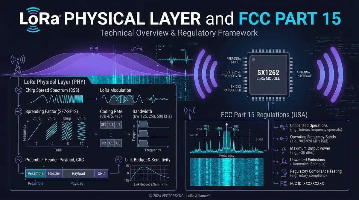
When builders first discover LoRa, it is usually through an off-grid text messenger like Meshtastic, a LoRaWAN soil-moisture sensor, or an SX1262 breakout board wired to an ESP32. The marketing promises are enticing: “10-mile range, license-free, 1 Watt of power, and military-grade encryption.”
Then you hit the workbench. You flash two identical development boards, put them on the same frequency, and they cannot hear a single packet. You measure your link with an SDR, and your transmitter is keying up for more than a second per burst. You check the FCC rules, and the “1 Watt” permission everyone quotes turns out to have strict bandwidth and dwell-time strings attached.
LoRa is not a radio service, an open standard, or an all-in-one mesh protocol. It is a patented physical-layer modulation (OSI Layer 1) owned by Semtech. To design nodes that deliver real packets in the field while staying completely lawful, you have to separate the physics of the chirp from the software running on top of it.
01 · The Envelope vs. The Letter: Chirp Spread Spectrum Mechanics
Think of LoRa as the envelope, not the letter inside. LoRa defines how raw digital bits turn into radio frequency energy traveling through the air. It says nothing about node addresses, mesh routing hops, encryption keys, or sensor telemetry. All of that is the letter, written by an upper-layer protocol like LoRaWAN, MeshCore, Meshtastic, or Reticulum.
Traditional sub-1GHz radios like the CC1101 or SI4463 use Frequency Shift Keying (2-FSK) or On-Off Keying (OOK). They hold a steady carrier and toggle between two discrete frequencies. If noise, building walls, or tree canopies push the signal below the background thermal noise floor, the receiver gets corrupted garbage. Standard 2-FSK links collapse the moment Signal-to-Noise Ratio (SNR) drops below .
LoRa replaces static tones with Chirp Spread Spectrum (CSS):
- Instantaneous Frequency Sweeps: A LoRa symbol is a continuous linear frequency sweep (a “chirp”) across the configured channel bandwidth (). An up-chirp sweeps from up to , wrapping around to the bottom edge when it hits the top. A down-chirp sweeps in reverse and acts as a frame delimiter.
- Cyclic Time Shifts: The transmitter encodes data by shifting the starting frequency of the sweep. With a Spreading Factor of , one symbol period is divided into discrete time increments. Each symbol carries exactly raw bits.
- The De-Chirping FFT: At the receiver, incoming RF energy is multiplied by a locally generated conjugate chirp. This “de-chirping” collapses the wideband sweep into a single, sharp frequency bin in an FFT.
- Sub-Noise Demodulation: Because de-chirping concentrates the symbol’s dispersed energy into one bin while spreading random noise across all bins, LoRa achieves a processing gain of approximately:
At SF7, processing gain is roughly . At SF12, it climbs to . This mathematical gain is why an SX1262 receiver can reliably demodulate packets all the way down to SNR — pulling signals cleanly out of the air when background thermal noise is ten times louder than the signal itself.
02 · The Three PHY Parameters: Spreading Factor, Bandwidth, and Airtime
Every LoRa link is governed by three physical settings configured in the transceiver’s SPI registers: Spreading Factor (SF), Bandwidth (BW), and Coding Rate (CR).
The core relationship governing symbol duration is:
Every step up in Spreading Factor doubles symbol time and adds approximately of link budget, at the cost of cutting data throughput in half.
Here is what that trade looks like at a standard bandwidth with a coding rate, based on Semtech SX1262 engineering specifications:
| Spreading Factor | Symbol Time () | Raw Bit Rate | Processing Gain | Demod SNR Limit | Sensitivity () |
|---|---|---|---|---|---|
| SF7 | |||||
| SF8 | |||||
| SF9 | |||||
| SF10 | |||||
| SF11 | |||||
| SF12 |
Doubling bandwidth from to halves the symbol time and doubles the data rate, but increases integrated thermal noise by , degrading sensitivity by .
The Airtime Reality Check
LoRa’s processing gain is not free. You pay for sensitivity in time on air. For a standard 20-byte payload with an 8-symbol preamble, explicit header, and CRC enabled:
| Configuration | Time on Air (ToA) | Relative Channel Occupancy |
|---|---|---|
| SF7, 125 kHz | (Baseline) | |
| SF9, 125 kHz | ||
| SF10, 125 kHz | ||
| SF11, 125 kHz | ||
| SF12, 125 kHz | ||
| SF7, 500 kHz | ||
| SF12, 500 kHz |
Look closely at the SF12 row. A single 20-byte packet keeps your transmitter keyed up for over 1.3 seconds. In that time window, a channel running SF7 could have completed twenty-three separate transmissions.
At symbol times of $16\text{ ms}$ or longer (SF11 and SF12 at $125\text{ kHz}$), temperature-induced crystal drift across a single symbol can break alignment. Always ensure the Low Data Rate Optimization (LDRO) bit is set in transceiver registers at both ends. Mismatched LDRO settings between transmitter and receiver cause silent packet loss.
03 · The Narrowband Trap: Why “1 Watt on 915 MHz” Is a Dangerous Myth
A common misconception in maker forums is that because the US 902–928 MHz band allows up to 1 Watt under FCC Part 15, you can crank any LoRa transmitter to on a single fixed frequency.
Under 47 CFR §15.247, the FCC provides two primary paths to transmit up to 1 Watt (30 dBm) conducted power. Neither path allows what most people assume:
Path A: Digital Modulation Systems (§15.247(a)(2))
To qualify for 1 Watt as a digital modulation system without frequency hopping, your transmitter must meet two strict technical conditions:
- Minimum 6 dB Bandwidth: The measured 6 dB bandwidth must be at least .
- Power Spectral Density (PSD): Conducted power spectral density cannot exceed in any band during continuous transmission.
The Narrowband Trap: A or LoRa signal physically cannot qualify for this path. A LoRa chirp is exactly as wide as its programmed bandwidth. A chirp cannot reach , no matter what spreading factor you select.
Furthermore, if you push 1 Watt () through a channel, your power is concentrated into a narrow slice. A flat-spectrum estimate yields approximately — blowing past the PSD limit by nearly . Only LoRa configurations even approach this digital modulation path.
Path B: Frequency Hopping Spread Spectrum (§15.247(a)(1)(i))
If your bandwidth is under , you can run up to 1 Watt only if the system implements genuine Frequency Hopping Spread Spectrum (FHSS):
- The system must use at least 50 hopping frequencies.
- The average time of occupancy on any frequency must not exceed 0.4 seconds within a 20-second period.
The Dwell Time Collision: Look back at our airtime table. An SF12 packet at takes to transmit. An SF11 packet takes . Both packets violate the 0.4-second maximum dwell time on a single hop.
A sweeping chirp is modulation, not frequency hopping. Merely using chirp spread spectrum does not make your radio a frequency hopper. A compliant FHSS LoRa system (like complete LoRaWAN US915 implementations) must hop pseudorandomly across channels, limit individual packet airtimes below 400 ms, and ensure equal channel utilization.
The Alternative: Radiated Field Strength under §15.249
If your firmware operates on fixed narrowband channels ( or ) without FHSS, it generally falls under 47 CFR §15.249.
Section 15.249 does not permit 1 Watt. It limits radiated field strength to measured at 3 meters. In an idealized free-space calculation, corresponds to approximately ( EIRP).
You cannot simply buy a 1-Watt amplifier, set your radio to SF12 on 915.0 MHz, and claim Part 15 compliance. Compliance is governed by the shape, bandwidth, and dwell time of your radiated waveform, not by the frequency band alone. Always check your module's official FCC grant and test reports using its FCC ID.
04 · The OSI Stack Separation & Why Identical SX1262s Can’t Hear Each Other
A recurring issue on the workbench is testing two nodes running different firmware and wondering why packets never arrive. Both boards have identical SX1262 transceivers, both are set to 915.0 MHz, and both use SF7 and 125 kHz. Yet the receiver’s packet counter never increments.
Here is why: network stacks live at completely different layers of the OSI model, and the radio hardware enforces low-level framing checks before passing any data to software:
| OSI Layer | Function | What Defines It | Examples |
|---|---|---|---|
| Layer 1 (PHY) | CSS modulation, chirps, SF, BW, CR, preamble, sync word, IQ polarity | Semtech Proprietary Silicon | SX1276, SX1262, SX1280, LR1121 |
| Layer 2 (Data Link / MAC) | Channel access, packet framing, addressing, CRC, dwell policies | Protocol MAC Specification | LoRaWAN MAC, Meshtastic framing, MeshCore frames, Reticulum RNode |
| Layer 3–4 (Network / Transport) | Topology, routing, multi-hop delivery, ACKs, retransmissions | Network Routing Engine | LoRaWAN Gateways/ChirpStack, Meshtastic managed flood, Reticulum transport |
| Layer 7 (Application) | User payload, messaging UI, sensor telemetry, application security | End-User Application | Meshtastic App, MeshCore Room Server, Sideband/LXMF, Home Assistant |
When a LoRa transceiver listens on a channel, it evaluates four physical framing primitives in silicon before triggering the SPI packet-ready interrupt:
- The Sync Word Register: Following the preamble up-chirps, the transmitter emits two modulated sync symbols. The receiver’s hardware correlator discards any frame whose sync word does not match its configuration.
0x12: The industry-standard “private” default used by many custom stacks and RNode.0x34: The LoRaWAN public network sync word.0x2B: The sync word used by Meshtastic firmware. A sync word mismatch produces complete silence at the host microcontroller.
- Preamble Length: A receiver needs a minimum number of un-modulated up-chirps to detect carrier energy, lock its phase, and align its symbol clock. If the transmitter uses an 8-symbol preamble while the receiver is cycling in a low-power duty-cycle mode that requires a 16-symbol preamble, detection fails intermittently.
- Explicit vs. Implicit Headers: In explicit header mode, the packet carries a short header detailing payload byte length, coding rate, and CRC presence. In implicit header mode, this header is omitted, and both radios must be hardcoded with identical byte lengths. An explicit transmitter talking to an implicit receiver will not agree on frame boundaries.
- IQ Polarity: LoRaWAN uses standard IQ polarity for uplink (node to gateway) and inverted IQ for downlink (gateway to node) to prevent nodes from demodulating other nodes’ transmissions. If IQ polarity is inverted, the receiver treats the signal as background noise.
Shared silicon and a shared frequency mean nothing without matching framing primitives and protocol parsers.
05 · Antennas, EIRP, and the 6 dBi Rule in 902–928 MHz
When range falls short, the instinctive workbench reaction is to buy a higher-gain antenna or an inline amplifier. But radiated RF power is strictly capped by physics and federal regulations.
What matters in the air is Effective Isotropic Radiated Power (EIRP):
Under 47 CFR §15.247(b)(4), where a 1 Watt (+30 dBm) conducted limit applies, the rules assume a maximum directional antenna gain of 6 dBi:
If you connect a high-gain directional antenna (such as a 9 dBi Yagi) in the 902–928 MHz band, you must reduce your conducted transmitter power by the exact amount the antenna gain exceeds 6 dBi:
Unlike the 2.4 GHz and 5.8 GHz bands, there is no fixed point-to-point antenna gain exception for 902–928 MHz under §15.247(c). The 4 Watt EIRP ceiling remains absolute.
Furthermore, under 47 CFR §15.204(c), an operator may only replace an authorized antenna with an antenna of the same type (e.g., dipole, collinear omni, patch) having equal or lower gain than the antenna tested with the module grant. An SMA connector is an RF interface, not a legal clearance to attach arbitrary antennas.
Before spending money on high-gain antennas or risking power violations, look at your spreading factor settings. Shifting from SF7 to SF12 improves receiver sensitivity from $-124.5\text{ dBm}$ to $-137.0\text{ dBm}$ — gaining $12.5\text{ dB}$ of link budget without increasing radiated power by a single microwatt. The trade is paid entirely in airtime.
06 · The Encryption Advantage & The Default-Key Illusion
One of the greatest engineering advantages of deploying on unlicensed Part 15 spectrum rather than Amateur Radio (Part 97) is payload encryption.
The Legal Framework: Part 15 vs. Part 97
Under Amateur Radio rules (47 CFR §97.113(a)(4)), operators are strictly prohibited from transmitting “messages encoded for the purpose of obscuring their meaning.” Furthermore, §97.311 enforces this same ban on amateur spread-spectrum signals. In 2013, the FCC issued Order DA 13-1918, explicitly dismissing a petition to create an encryption exception for emergency preparedness and disaster training. If you transmit under Part 97 rules, every packet must be plaintext and periodically identified with your station callsign.
Under FCC Part 15 unlicensed spectrum, the rules regulate the physical waveform — occupied bandwidth, dwell time, power spectral density, and out-of-band harmonics. Part 15 contains no restriction on payload content.
You are legally permitted to transmit:
- AES-128 and AES-256 encrypted telemetry from home sensors, power monitors, and gates.
- End-to-end encrypted messaging between authorized users.
- Commercial and business traffic without amateur station licensing or callsign broadcasts.
The Operational Trap: Encrypted Private
While Part 15 legally protects your right to encrypt, popular community firmware often creates a false sense of privacy.
Several widely used mesh platforms ship with publicly known default pre-shared keys (PSKs):
- Meshtastic: The default
LongFastprimary channel uses a well-known, published AES-128 key (0x11, 0x11, 0x11...). Any device running the stock app within radio range automatically decrypts and reads every message and GPS beacon. - MeshCore: Public root channels and hashtag channels use pre-shared keys that are either publicly hardcoded or deterministically generated from the channel name string.
- Packet Headers: In almost all mesh implementations, network-layer routing headers, node numbers, and hop counts are transmitted in the clear so intermediary relay nodes can route the packet without holding the decryption key.
If you are deploying a sensor network or team messaging link that handles sensitive telemetry, you must generate a unique, cryptographically random PSK and exchange it out-of-band. Legal permission to encrypt does not equal operational secrecy out of the box.
07 · Field Checklist & Common Misconceptions Corrected
Before ordering hardware or mounting an antenna on your roof, use this comparison to separate marketing claims from technical and regulatory realities:
| Common Community Claim | Physical & Regulatory Reality | Controlling Authority |
|---|---|---|
| “LoRa is an unlicensed radio service.” | LoRa is a proprietary physical-layer modulation. Ordinary consumer operation in the US is authorized under FCC Part 15 unlicensed device rules. | 47 CFR §15.1, Semtech AN1200.22 |
| “915 MHz allows 1 Watt on any channel.” | 1 Watt conducted requires either 6 dB bandwidth with PSD, or channel FHSS with dwell. Fixed channels cannot use this shortcut. | 47 CFR §15.247(a) |
| “LoRa is spread spectrum, so it’s a frequency hopper.” | CSS sweeps frequency within its modulation bandwidth. Frequency hopping is an upper-layer channel-selection mechanism. A chirp is not a hop. | 47 CFR §15.247(g) |
| “SF12 is just ‘long range mode’ with no downside.” | SF12 takes longer on air than SF7 ( for 20 bytes). It can saturate channels, drain batteries, and exceed FHSS dwell limits. | Semtech SX1262 Datasheet, §15.247(a)(1) |
| “Any antenna is legal if EIRP stays under 4 Watts.” | Section 15.204 restricts replacement antennas to the same type and equal/lesser gain as documented in the module’s equipment authorization. | 47 CFR §15.204(c) |
| “Any two 915 MHz LoRa nodes can communicate.” | Incompatible sync words (0x12 vs 0x34 vs 0x2B), preamble lengths, header modes, or framing protocols will block reception entirely. | Semtech AN1200.13 |
| “A ham license lets you run encrypted high-power LoRa.” | Operating under Part 97 amateur rules strictly forbids messages encoded to obscure their meaning (§97.113(a)(4)), regardless of power. | 47 CFR §97.113, FCC DA 13-1918 |
| “Default mesh channels provide confidential privacy.” | Stock firmware channels use published or derivable keys. Anyone with an identical radio in range decodes that traffic. | Project Security Docs |
The Builder’s Pre-Flight Checklist
Before you finalize a LoRa node deployment, verify these six physical checkpoints on the bench:
- Verify the Module FCC ID: Search the FCC Equipment Authorization database for your transceiver module’s ID. Confirm the grant covers your operating frequencies, modulation types, and output power.
- Match Framing Primitives: Verify sync word registers (
0x12,0x34,0x2B), preamble length, and explicit header modes between both transmitter and receiver firmware. - Calculate Airtime & Channel Capacity: Use the symbol time formula () to calculate packet time on air. Keep payloads compact to prevent channel saturation and respect dwell limits.
- Tune the Antenna with a VNA: Measure your antenna on a NanoVNA at 915 MHz before installation. Ensure (SWR ) to protect the transceiver’s output stage and maximize radiated efficiency.
- Set Low Data Rate Optimization: Ensure LDRO is enabled whenever symbol duration exceeds (SF11 and SF12 at ).
- Generate Custom Encryption Keys: If transmitting private telemetry or secure messages under Part 15, generate an independent, cryptographically random key rather than relying on default firmware channels.
LoRa is one of the most capable tools in modern RF engineering when you design with its physical boundaries in mind. Keep your spreading factors lean, verify your framing registers, stay within Part 15 spectral rules, and let the physics of chirp spread spectrum carry your telemetry through the noise.